Date:2022-12-12 Click:939次
Date:2022-12-12 Click:808次
Date:2022-12-12 Click:591次
Date:2022-12-12 Click:711次
Date:2022-12-12 Click:993次
Date:2022-12-12 Click:929次
Date:2022-12-12 Click:782次
Date:2022-12-12 Click:974次
Date:2022-12-12 Click:535次
Date:2022-12-12 Click:881次
Date:2022-12-12 Click:620次
Date:2022-12-12 Click:971次
Date:2022-12-12 Click:707次
Date:2022-12-12 Click:777次
Date:2022-12-12 Click:863次
Date:2022-12-12 Click:566次
Date:2022-12-12 Click:991次
I. Overview
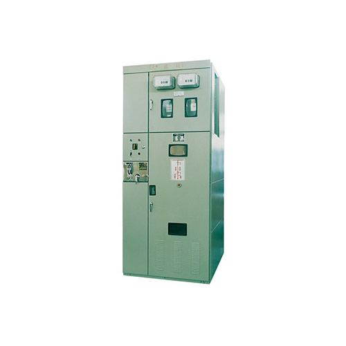
XGN2-10 is a box-type fixed metal-enclosed switchgear (hereinafter referred to as switch cabinet) with a rated voltage of 12kV. It is used for receiving and distributing electric energy in three-phase AC 50Hz systems with voltage levels of 12kV and below. It is especially suitable for frequent operations. In this case, the bus system is single bus and single bus with bypass.
This switch cabinet complies with the requirements of GB3906 and IEC298, and has the "five prevention" interlocking functions proposed by the two departments.
The circuit breaker and operating mechanism combinations used in this switch cabinet are as follows:
ZN12-10 is equipped with CT100 special spring operating mechanism;
ZN28-10 is equipped with CD10Ⅱ electromagnetic operating mechanism, CT8Ⅱ spring operating mechanism, CT19 spring operating mechanism;
SN10-10 (Ⅰ, Ⅱ) is equipped with CD10Ⅱ electromagnetic operating mechanism, CT8Ⅱ spring operating mechanism and other series.
Its isolating switch adopts GN30-10 rotary isolating switch and GN22-10 isolating switch series according to the requirements of the fixed cabinet.
2. Normal use conditions
a) Indoor
b) Ambient air temperature: upper limit +40; lower limit -25℃
c) The altitude does not exceed 1000m (ZN28-10 with CD10 or CT8 can reach 2500m)
d) Relative humidity: the daily average value is not greater than 95%; the monthly average value is not greater than 90%.
e) The earthquake intensity does not exceed 8 degrees
f) Places without risk of fire, explosion, serious pollution, chemical corrosion and severe vibration.
Note: If the above normal usage conditions are exceeded, users can negotiate with the manufacturer to take corresponding measures according to their requirements.
3. Technical parameters
Technical parameters of switch cabinet (see Table 1)
Table 1
No | Item | Unit | Parameter | ||||
1 | rated voltage | kV | 3.6 , 7.2 , 12 | ||||
2 | rated current | A | 630,1000,1600,2000,3150 | ||||
3 | rated frequency | Hz | 50 | ||||
4 | Rated insulation level | lightning strike Withstand voltage | phase and ground | kV | 75 | ||
Isolate fracture | 85 | ||||||
1min power frequency Withstand voltage | phase and ground | 42 | |||||
Isolate fracture | 48 | ||||||
5 | Rated short-time withstand current | kA | 20 | 31.5 | 40 | ||
6 | Rated peak withstand current | kA | 50 | 80 | 100 | ||
7 | Rated short circuit making current | kA | 50 | 80 | 100 | ||
8 | Rated short circuit breaking current | kA | 20 | 31.5 | 40 | ||
9 | Rated short circuit duration | s | 4 | ||||
10 | Protection level | IP2X | |||||
11 | busbar system | Single busbar (single busbar with bypass) | |||||
12 | Operation mode | Electromagnetic or spring energy storage type | |||||
13 |
Various cabinet dimensions (width × depth × height)
| mm | Small current cabinet of 1600A and below: 1100×1200×2650 High current cabinet above 1600A: 1200×1200×2650 Overhead outlet cabinet: 1100(1200)×1600×2650 Single busbar with bypass: 1100(1200)×1900×2650 | ||||
Circuit breaker technical parameters (see Table 2)
Table 2
No | Item | Unit | SN10-10 | ZN28-10 | ZN12-10 |
1 | rated voltage | kV | 10 | ||
2 | rated frequency | Hz | 50 | ||
3 | rated current | A | 630,1000 | 1250,1600 | 1250,1600,3150 |
4 | Rated short circuit breaking current | kA | 16,31.5 | 31.5 | 31.5,40 |
5 | Rated short circuit making current (peak value) | kA | 40,80 | 80 | 80,100 |
6 | Rated peak withstand current | kA | 40,80 | 80 | 80,100 |
7 | Rated short-time withstand current | kA | 16,31.5 | 31.5 | 31.5,40 |
8 | Rated short circuit duration | s | 4 | ||
9 | Mechanical life | time | 2000 | 10000 | |
10 | Rated short circuit current breaking times | 20 | 30 | ||
Main technical parameters of the operating mechanism (see Table 3-Table 6)
Table 3 Main technical parameters of CD10Ⅱ DC electromagnetic operating mechanism
No | Item | unit | CD10Ⅱ | ||
1 | rated voltage | Closing coil | V | 110,220 | |
Opening coil | 24,48,110,220 | ||||
2 | rated current | Close | 110 | A | 240 |
220 | 240 | ||||
open | 24 | 37 | |||
48 | 18.5 | ||||
110 | 5 | ||||
220 | 2.5 | ||||
Table 4 Main technical parameters of CT100 special spring operating mechanism
No | Item | Unit | Parameter |
1 | Energy storage motor power supply voltage | V | —~110,—~220 |
2 | Opening and closing electromagnet voltage | —~110,—~220 | |
3 | Voltage of voltage loss release | —~110,—~220 | |
4 | Energy storage time | s | ≤15 |
5 | Overcurrent tripping rated current | A | 2.5 |
Table 5 Main technical parameters of CT8Ⅱ spring operating mechanism
No | Item | Unit | Parameter |
1 | Energy storage motor power supply voltage | V | —~110,—~220, ~380 |
2 | Opening and closing electromagnet voltage | —~110,—~220,~380,—48 | |
3 | Voltage of voltage loss release | ~110,~220,~380 | |
4 | Energy storage time | s | ≤5 |
5 | Overcurrent tripping rated current | A | 5 |
Table 6 Main technical parameters of CT19 spring operating mechanism
No | Item | Unit | parameter |
1 | Energy storage motor power supply voltage | V | —~110,—~220 |
2 | Opening and closing electromagnet voltage | —~110,—~220,~380,—48 | |
3 | Voltage of voltage loss release | —~110,—~220,~380,—48 | |
4 | Energy storage time | s | ≤10 |
5 | Overcurrent tripping rated current | A | 5 |
Technical parameters of the isolating switch (see Table 7)
table7
No | Item | Unit | GN30-10 GN30-10D | GN30-10 GN30-10D | GN30-10 GN30-10D | GN22-10 | GN22-10 |
1 | rated voltage | kV | 10 | ||||
2 | rated current | A | 400 | 630 | 1000 | 2000 | 3150 |
3 | Rated peak withstand current | kA | 31.5 | 50 | 80 | 100 | 105 |
4 | Rated short-time withstand current | kA | 10.5 | 20 | 31.5 | 40 | 50 |
5 | Rated short circuit duration | s | 4 | ||||
6 | Lightning impulse withstand voltage | kV | Phase to phase and ground: 75, isolation fracture: 85 | ||||
7 | Short-time power frequency withstand voltage | Phase to phase and ground: 42, isolation fracture: 48 | |||||
Grounding switch technical data (see Table 8)
table8
No | Item | Unit | JN2-10 |
1 | rated voltage | kV | 10 |
2 | Lightning impulse withstand voltage | 75 | |
3 | 4s thermal stable current | kA | 31.5 |
4 | dynamic stable current | 80 | |
5 | 1min power frequency withstand voltage | kV | 42 |
Current transformer technical parameters (see Table 9--Table 10)
Table 9 Technical parameters of LZBJ12-10 current transformer
Rated primary current (A) | Rated secondary current (A) | Rated short-term heat Current (kA) | Dynamic stable current (kA) | Rated secondary load(VA) | 10P level accurate Limit coefficient (times) | |
0.5,1 Level; | 10P level | |||||
5 | 5 | 2 | 5 | 10 | 15 | 10 |
10 | 4 | 10 | ||||
15 | 6 | 15 | ||||
20 | 8 | 20 | ||||
30 | 10 | 25 | ||||
40 | 16 | 40 | ||||
50 | 20 | 50 | ||||
75 | 33 | 80 | ||||
100~300 | 45 | 100 | ||||
400~800 | 45 | 100 | ||||
1000~1500 | 63 | 130 | ||||
Table 10 Technical parameters of LMZJ1-10 current transformer
No | Item | unit | data | |
1 | Rated primary current | A | 2000,3150,4000 | |
2 | Rated secondary current | 5 | ||
3 | Rated frequency | Hz | 50 | |
4 | Rated secondary load | 0.5 level | VA | 50 |
10P level | 60 | |||
5 | 10P level accurate limit coefficient | times | 15 | |
Technical data of voltage monitoring device (see Table 11)
table 11
No | item | unit | ZDJ□-6 | ZDJ□-10 | DXN3-4 |
1 | Rated voltage | kV | 6 | 10 | 10 |
2 | Lightning impulse withstand voltage | 57 | 75 | 75 | |
3 | Short-time power frequency withstand voltage (1min) | 32 | 42 | 42 | |
4 | Minimum starting voltage of neon lamp (primary voltage) | 3 | 5 | 5 | |
5 | Maximum operating voltage of neon lamp (primary voltage) | 7.2 | 12 | 12 |
The technical parameters of the arrester are shown in Table 12
Table 12
Model | Voltage | HY2.5W1 -7.6/19 | HY2.5W1 -12.7/31 | HY5WR2 -10/27 | HY5WR2 -17/45 | HY5WZ2 -10/27 | HY5WZ2 -17/45 | HY5WS2 -10/30 | HY5WS2 -17/50 |
usage | Motor type | Capacitor type | Power station type | Distribution type | |||||
System rated voltage | kV | 6 | 10 | 6 | 10 | 6 | 10 | 6 | 10 |
Arrester rated voltage | kV | 7.6 | 12.7 | 10 | 17 | 10 | 17 | 10 | 17 |
Residual voltage (8/20)μS5kA | kV | ≤19 | ≤31 | ≤27 | ≤45 | ≤27 | ≤45 | ≤30 | ≤50 |
Arrester continuous voltage | kV | 4 | 6.6 | 7.6 | 12.7 | 7.6 | 12.7 | 7.6 | 12.7 |
Circuit breaker room:
The circuit breaker room is in the lower part of the cabinet, and the transmission of the circuit breaker room is connected by a pull rod and the operating mechanism; the lower terminal of the circuit breaker is connected to the current transformer, and the current transformer is connected to the terminal of the lower isolating switch; the upper terminal of the circuit breaker Connected to the terminals of the upper isolating switch, the circuit breaker chamber is also equipped with a pressure relief channel. If an internal arc occurs, gas can release the pressure through the exhaust channel.
Cable room:
The cable room is behind the lower part of the cabinet. The cable room supports insulators that can be equipped with probes for voltage monitoring devices. The cables are fixed on the brackets. When the main wiring is a contact plan, this room is the contact cable room.
Locking device to prevent misuse:
The operating mechanism of the circuit breaker is installed on the left side of the front. Above it is the operating and interlocking mechanism JSXGN of the isolating switch. It and the operating mechanism use mandatory machinery. The front door and back door are controlled by program locks. The entire interlock has a certain program. When using it, it must be operated according to the program, otherwise it cannot be operated. The specific action principle is as follows:
Power supply operation (inspection → operation)
If the maintenance has been completed and power needs to be supplied, the operating procedures are as follows:
Close and lock the back door, take out the key and close the front door. Move the small handle from the inspection position to the "breaking and locking" position. At this time, the front door is locked and the circuit breaker cannot be closed. Use the operating handle to insert into the grounding switch operating hole. Pull up and down to put the grounding switch in the open position, take off the operating handle and insert it into the operating hole of the isolating switch, push it from bottom to up, so that the isolating switch is in the closing position (operate the upper isolating switch first or operate the lower isolating first) The switch
is determined by the user's requirements), take out the operating handle, and move the small handle to the "working" position. At this time, the circuit breaker can be closed and put into operation.


 简体中文
简体中文 English
 French


