Date:2022-12-12 Click:622次
Date:2022-12-12 Click:968次
Date:2022-12-12 Click:620次
Date:2022-12-12 Click:653次
Date:2022-12-12 Click:759次
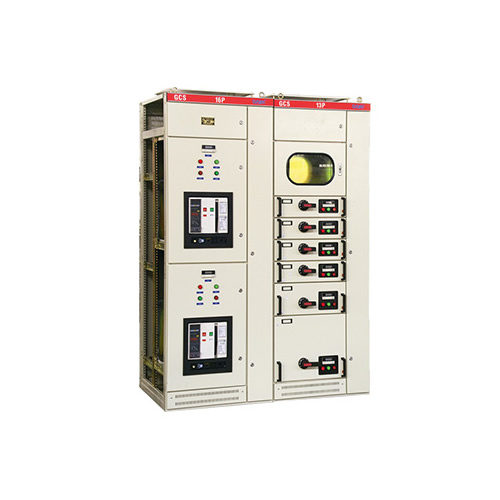
·Overview
The GCS type low-voltage withdraw-able switch (hereinafter referred to as the device) is designed and developed by the two joint design teams according to the requirements of industry authorities, power users and design units. It is in line with national conditions, has high technical performance indicators, and can adapt to the development of the power market. Low-voltage withdraw-able switch is needed and can compete with existing imported products. This device has been widely selected by power users. The device is suitable for power distribution systems in power plants, petroleum, chemical industry, metallurgy, textiles, high-rise buildings and other industries. In large power plants, petrochemical systems and other places with a high degree of automation that require computer interfaces, as a generator with a three-phase AC frequency of 50 (60) Hz, a rated operating voltage of 380V (400V, 600V), and a rated current of 4000A and below. , low-voltage complete power distribution device used for power distribution, motor centralized control, and non-power compensation in the power supply system.
·Product model and meaning
G C S - □ - □
G——Closed switch cabinet
C——Draw-out type
S——Senyuan Electrical Systems
□——Main circuit plan number
□——Auxiliary circuit plan number
.GCS technical parameters
Serial number project parameters
1 Main circuit rated voltage (V) AC 380 (400), (660)
2 Auxiliary main circuit rated voltage (V) AC 220, 380 (440) DC 110, 220
3Rated frequency (Hz)50(60)
4Rated insulation voltage (V) 660 (1000)
5Rated current (A) horizontal bus ≤ 4000
Vertical Busbar (MCC)1000
6 Busbar rated short-time withstand current (kA/1s) 50, 80
7 Busbar rated peak withstand current (kA/1s) 105, 176
8 Power frequency test voltage (V/1min) main circuit 2500
Auxiliary circuit 1760
9-bus three-phase four-wire A.B.C.PEN
Three-phase five-wire system A.B.C.PE.N
10 protection level IP30, IP40
Structural features
1. The main frame of the GCS device of Daya Electric Group is made of 8MF steel, and the frame adopts two forms: assembled frame and partial welding. There are mounting hole modules (E=20mm) on the main frame.
2. The functional rooms of the device are strictly separated. The compartments are mainly divided into functional unit rooms, busbar rooms, and cable rooms. The functions of each unit are relatively independent.
3. Functional unit
a. The drawer height module is 160mm and is divided into 5 specifications: 1/2 unit, 1 unit, 3/2 unit, 2 unit, and 3 unit. The unit circuit rated current is below 400A.
b. The drawer changes only in the height dimension, and its width and depth dimensions remain unchanged. Drawers with the same functional unit have good interchangeability.
c. Each MCC cabinet can be installed with up to 11 one-unit drawers or 22 1/2-unit drawers. More than one unit of drawers adopts a multi-functional back panel.
d. The drawer inlet and outlet wires use different numbers of plug-ins with the same specification chip structure according to the current size.
e. The connection between the drawer of the 1/2 unit and the cable room adopts the ZJ-2 type adapter with a backplate structure.
f. The connection between the unit drawer and the cable room adopts the same size rod type or tube type ZJ-1 type adapter according to the current classification.
h. The drawer unit does not have a mechanical interlocking device.
4. The feeder cabinet and motor control cabinet are equipped with dedicated cable compartments. The connection between the functional unit room and the cable room is realized through an adapter or an adapter copper bar, which not only improves the reliability of the cable, but also greatly facilitates users. Installation and maintenance of cables.
The cable compartment is available in two width sizes (240mm and 440mm), depending on the number of cables, cross-section and user requirements for ease of installation and maintenance.
5. The number of auxiliary contact pairs of functional units of the device is 32 pairs for one unit and above, and 20 pairs for 1/2 unit, which can meet the needs of automation users and computer interfaces.
6. Taking into account the general safety of dry-type transformers and the economy of oil-immersed transformers, the device can be easily formed into a group with dry-type transformers, and can also be easily connected to the low-voltage busbar of oil-immersed transformers.
7. With drawer as the main body, it has both pull-out and fixed styles, which can be mixed and combined for any choice.
8. The device is designed according to three-phase five-wire and three-phase four-wire systems. The design department and users can easily choose the PE+N or PEN method.
9. The protection level of the cabinet is IP30 or IP40, which can be selected according to user needs.
Installation and use
After the product arrives, you should first check whether the packaging is intact. If any problems are found, you should promptly notify the relevant departments to keep business records, jointly analyze the reasons, and prepare visas and follow-up procedures. Products that are not to be installed immediately should be placed in an appropriate place and properly stored according to the requirements of normal use and temporary storage of electrical equipment.
1. The product should be installed according to the installation diagram. The basic channel steel and the bolts used for bolt fixation shall be prepared by the user. If the surface of the main busbar connection ground is uneven due to transportation, storage, etc., then connect and tighten it.
2. When the devices are installed alone in a row, their verticality, unevenness of the cabinet surface, and deviation of the cabinet door gaps should be as shown below
3. Inspection and testing after product installation and before operation
a. Check whether the cabinet surface paint or other covering materials (such as spray plastic) are damaged and whether the cabinet is dry and clean.
b. Whether the operation of electrical components is flexible and there should be no jamming or excessive operating force.
c. Whether the main and auxiliary contacts of the main electrical appliances are connected reliably and accurately.
d. The drawer or pull-out mechanism should be flexible, light, and free of jamming and collision.
e. The center lines of the dynamic and static contacts of the drawer or pull-out structure should be consistent, and the contact contact should be tight. The insertion depth of the main and auxiliary contacts should meet the requirements. The mechanical interlocking or electrical interlocking device should be installed correctly, and the locking or releasing should be reliable.
f. Drawers of the same size should be able to be easily drawn from each other. No jamming or collision.
g. The ground contact between the drawer and the cabinet should be in close contact. When the drawer is pushed in, the ground contact of the drawer should contact before the main contact. When the drawer is pulled out, the ground contact should be disconnected after the main contact.
h. The scale setting of the instrument, the transformation ratio and polarity of the transformer should be correct.
i. The core specifications of the fuse should meet the requirements of the engineering design.
j. The rated value and shorthand value of the relay protection should be correct and the operation should be reliable.
k. The insulation resistance value measured with a 1000 megger shall not be greater than 1MΩ.
l. The connection of each busbar should be good, and the installation of insulation supports, installation parts and other accessories should be firm and reliable.
4. Precautions for use
a. The device is a low-voltage distribution cabinet that is not installed against the wall, operated from the front, and maintained on both sides. Only qualified professionals can enter or open the cabinet maintenance channels and cabinet doors for operation, inspection and maintenance.
b. After multiple openings and closings of air circuit breakers and molded case circuit breakers, especially after short circuit opening and closing, the contacts will be partially burned and carbon substances will be produced, which will increase the contact resistance. They should be used as relays. Instructions for performing repairs and overhauls.
c. After installation and maintenance, it is necessary to strictly check that the isolation status between compartments and functional units has been restored to ensure good functional separation of the device and prevent the expansion of faults.
Ordering instructions
The order contract contains the following contents:
1. The product model includes the main circuit plan number and the auxiliary circuit plan number;
2. Main circuit system combination sequence diagram;
3. Electrical schematic diagram of auxiliary circuit


 简体中文
简体中文 English
 French


